Excavator Throttle Motor AC2000 Maintenance Method
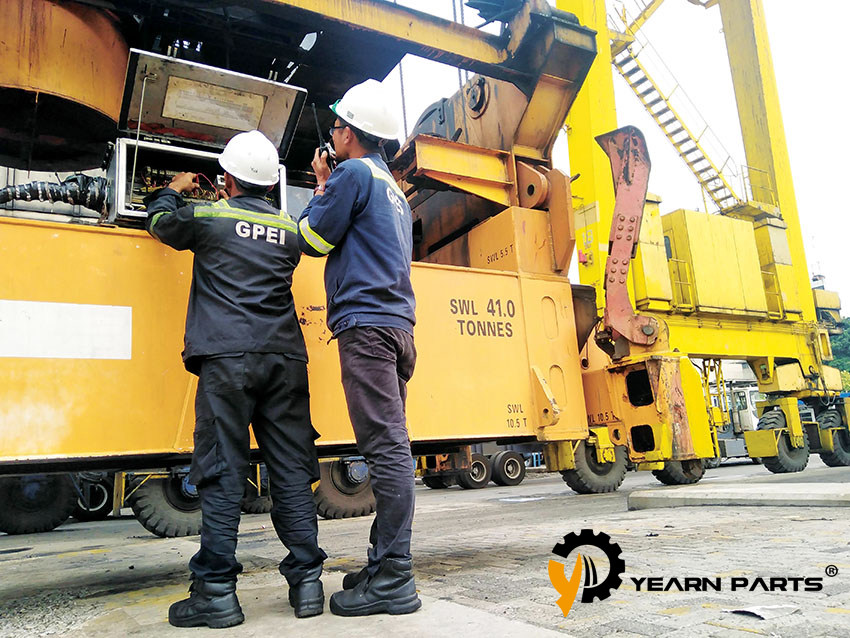
Excavator Throttle Motor AC2000 Maintenance Method
1.Throttle Motor Failure Phenomenon
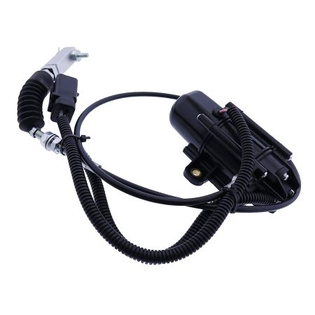
Test the resistance change of the throttle motor at different positions and use 24V to start the motor. However, when the motor is started with the same direction of driving voltage, the motor throttle flexible shaft extends to a certain length and then automatically retracts.
It is suspected that the hoist limit clip inside the motor is broken (similar to the bolt stripping), causing the flexible shaft to move in the opposite direction. In order to study the root cause of this motor failure, the motor was disassembled.
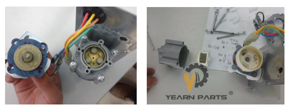
2. Disassembly of the outer casing To disassemble the outer casing, you only need to remove the six bolts on the outer ring.
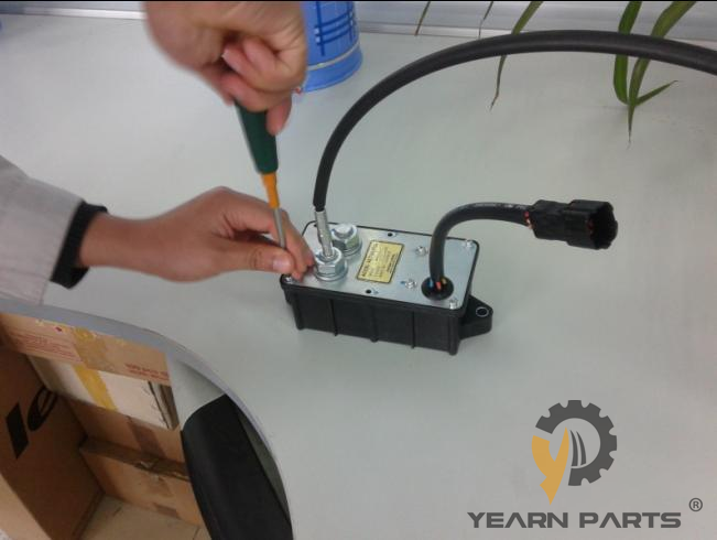
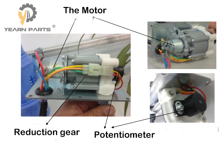
3. Disassembly of the outer shell.The internal structure is mainly composed of drive motor, planetary reduction mechanism, potentiometer and other parts.
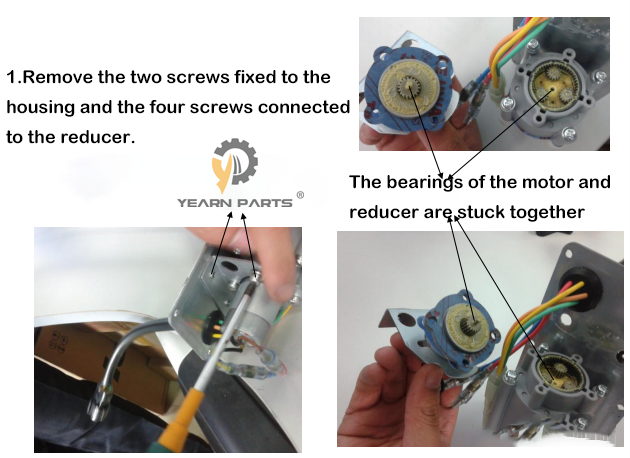
4. Disassembly of the drive motor.Remove the two bolts fixed to the housing and the four bolts connected to the reducer.
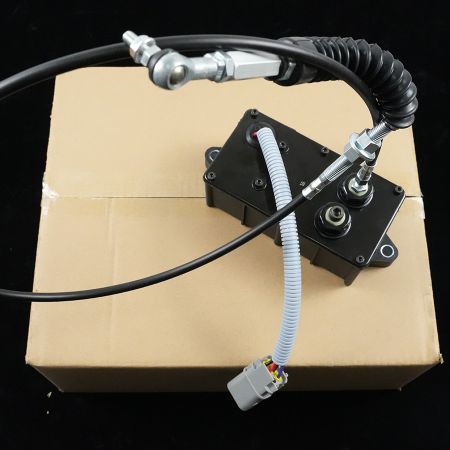
5.Disassembly of the reducer.The reducer has two-stage planetary reduction mechanisms. The first-stage reduction mechanism can be seen after removing the motor. After removing the gray shell, the second-stage planetary reduction mechanism is exposed.

6. Disassembly of potentiometer.The potentiometer is on the back of the reducer, just remove the two screws.
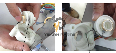
7. Found the cause of the fault
The clip of the winch limit was broken, causing the motor to not lock when it reached the maximum displacement from the minimum displacement, and it would continue to rotate, but the wire would be retracted. (When the motor is at the minimum displacement, the steel wire is wound around the winch, and when the motor is at the maximum displacement, the wire on the winch will be completely released. Therefore, if the winch continues to rotate, the wire will be reversed and wound around the winch.)
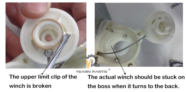
8. Some other questions
1. When the motor does not rotate, how is the travel of the wire locked? As shown in the figure below, there are three gears A, B, and C. These two circles of gears each hold half of the middle gear. Gear A is fixed to the gray shell and cannot rotate; gear C only rotates with the middle shaft and can rotate close to gear A. When the middle shaft, that is, the motor, does not rotate, gear C will be stuck by gear A; gear B can rotate with gear C, but conversely when the motor does not rotate, gear C is stuck by gear A, and gear B will also be stuck by gear C and cannot rotate.
2. About the reduction ratio. The reducer has a two-stage planetary reduction mechanism. The speed ratio of the first-stage reduction mechanism is 48:18; the second-stage reduction mechanism cannot be disassembled in the middle part, so I don’t know what the structure is inside, but the speed ratio roughly measured by the number of rotations is about 96:1. The overall speed ratio is 256
